No products in the cart.

Queenbee Z axis assembly
QueenBee PRO style CNC Z axis assembly BOM
| Product | Price | Qty | ||
|---|---|---|---|---|
 | MGN15 linear guide - 250mm | $10.62 | 2 | Add to Cart |
| | MGN15C linear bearing | $14.87 | 4 | Add to Cart |
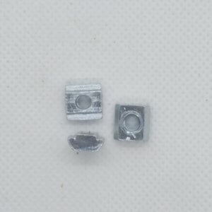 | Sliding T-Nut for 2020 and V-slot profiles - M3 | $0.16 | 12 | Add to Cart |
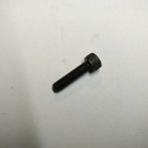
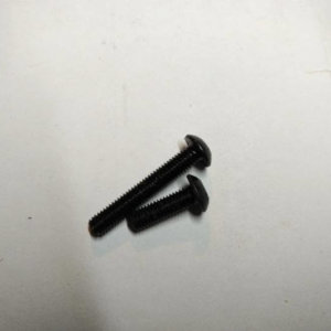 | Button Head Cap Screw
| $0.16 | 12 | Add to Cart |
| | C-beam - 250mm | $8.50 | 1 | Add to Cart |
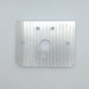
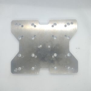 | Queenbee Pro type Z plate | $21.24 | 1 | Add to Cart |
| | TR8*8-2p 4 start anti backlash nut block in Delrin | $8.50 | 1 | Add to Cart |
| | 18mm Z spacer block | $6.37 | 1 | Add to Cart |
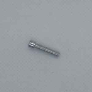
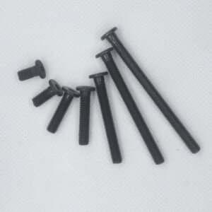 | Low profile screw M5 - 35mm | $0.37 | 2 | Add to Cart |
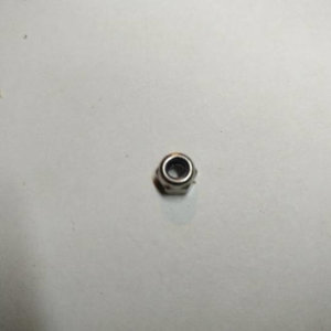 | Nylon Insert Lock Nut - M5 In stock | $0.27 | 2 | Add to Cart |
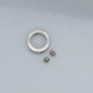 | lock collar - 8mm | $2.12 | 2 | Add to Cart |
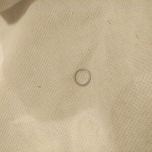 | 8mm precision shim | $0.53 | 2 | Add to Cart |
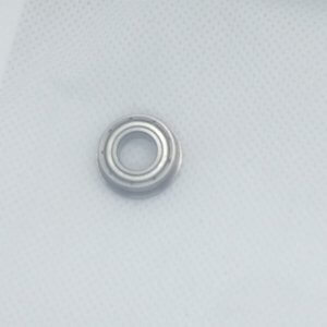 | F688ZZ flanged bearing | $3.19 | 2 | Add to Cart |
| | 281mm ACME leadscrew | $15.93 | 1 | Add to Cart |
 | Socket Head Screw
In stock | $0.27 | 4 | Add to Cart |
 | Z-Axis End Mount Motor Bottom | $8.50 | 1 | Add to Cart |
 | Z-Axis End Mount Motor Top | $10.62 | 1 | Add to Cart |
 | Small head socket screw
| $0.15 | 1 | Add to Cart |
| Add All To Cart |
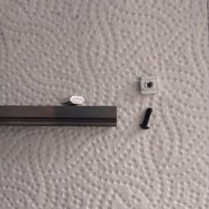
1. The linear rails
Use the M3 10mm screws and the M3 sliding (or post insertion) nuts.
Attach them then to the 250mm C beam:
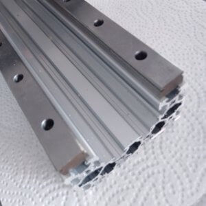
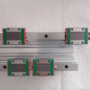
And slide on the MGN15 bearings – be careful not to loose the bearing balls:
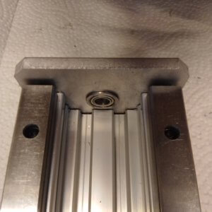
Then put the flanged bearings into the end plates:
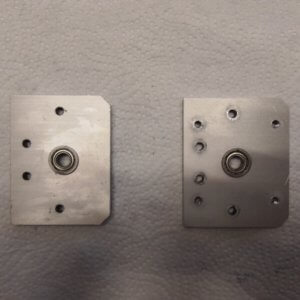
And attach the end plates at the end of the C beam, with M5 15mm screws:
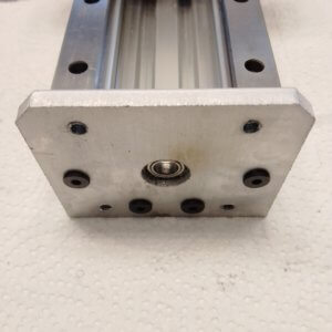
The flange of the flanged bearings should be inside:
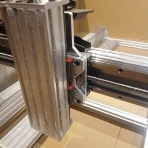
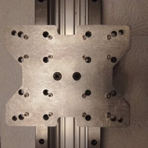
2. Z gantry
Attach the anti backlash nut bloc to the Z plate with some space in-between: either by using the plastic spacer block, or else by using spacer and shims totalling 17mm:
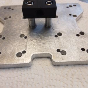
Use 2 M5 lock nuts and 2 35mm (or 40mm) screws for attaching that anti-backlash nut block.
And then connect the Z plate to the bearings (the anti backlash nut facing into the C beam), by using M3 x 12mm small head screws:
3. The leadscrew
Use the 8 leadsrew, with at both ends an 8mm precision shim and 8mm lock collar:
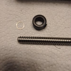
But put them on, only when the leadscrew is inserted into the assembly:
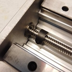
And then put it onto the flange of the flanged bearing:
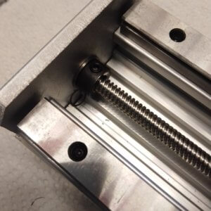
Do this at both ends and make sure there is a bit sticking out at the end plate that has 4 tapped holes, this will be to connect the coupler for the motor:
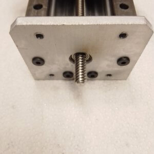
4. Mate the Z plate with the X plate
Use screws with a 15 to 20mm screw length – the motor side of the Z axis should be at the top: