
No products in the cart.

Queenbee Y axis assembly
QueenBee PRO style CNC Y axis assembly BOM

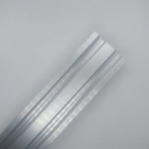
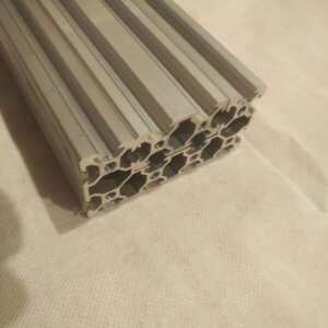
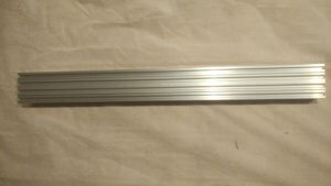
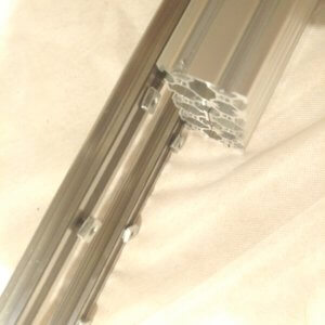
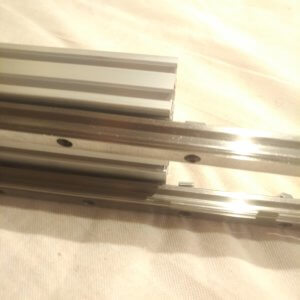
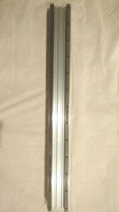
1. Combine the 2040 and C beam rails
Push the 2040 rails into the C beam rails:
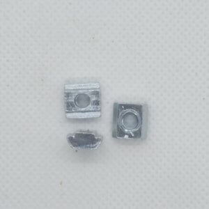
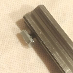
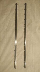
2. Prepare the linear guides
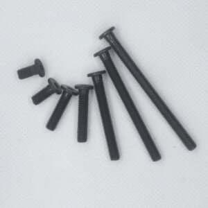
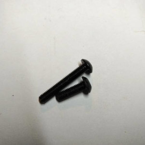
Put an M4 x 14mm screw in each hole, and a sliding t nut – do not tighten these yet:
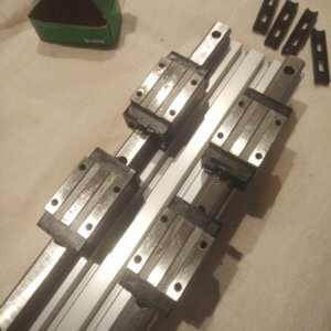
3. Attach linear guides to the C beams:
Slide the linear guides onto the C beams and fixate them:
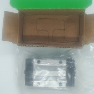
4. Put on the linear bearings:
Slide the linear bearings onto the linear guides – keep them really next to them when transferring from the plastic onto the linear guides so that no metal balls escape:
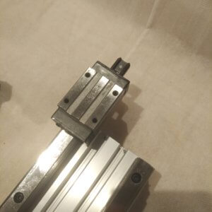
Do this 2 per linear guide:
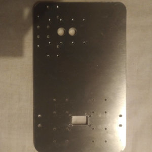
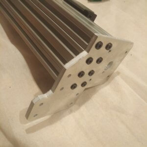
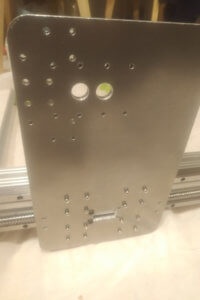
5. Attach end plates at the ends
Watch the orientation relative to the side with the linear guides – use 15mm low profile screws:
6. Attach to the spoilerboard
If you want, you can now already attach the Y axis rails to the spoiler board you just made, via 10mm low profile screws and T slot nuts. You can also do this later:
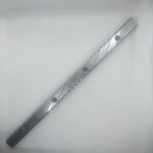
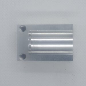
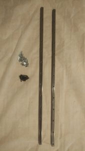
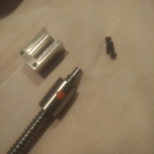
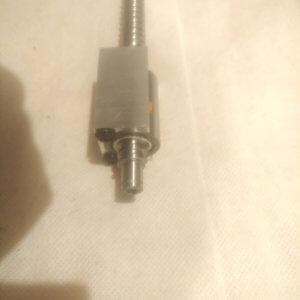
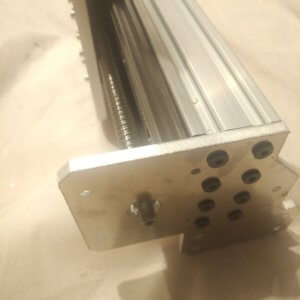
8. Prepare the Y axis ballscrews
This step is a bit different from the other QueenBee PRO assembly instructions that you will find elsewhere. Because we ship with ballscrews, these need to be prepared.
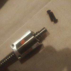
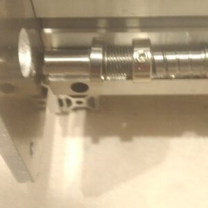
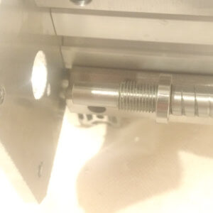
At a ballscrew bearing holder and watch closely the orientation of the ballscrew bearing holder relative to the machined ends of the ballscrew – do as in the picture and attach with M4 x 14mm or M4 x 16mm screws:
DO NOT REMOVE THE BALLSCREW BEARING FROM THE BALLSCREW. IT WILL NOT BE POSSIBLE TO USE IT AGAIN (tiny little balls will fall out and get lost)
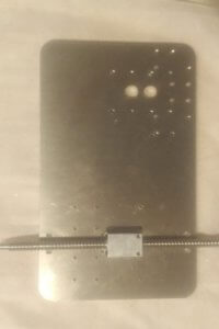
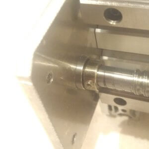
7. Attach the ballscrews to the Y axis plates
This step is a bit different from the other QueenBee PRO assembly instructions that you will find elsewhere. Because we ship with ballscrews, these CANNOT be separated from the round ballscrew bearings.
So with the ballscrew bearings staying on the ballscrews, the holders were prepared in the previous step and now we will attach these to the Y axis plates with 20mm low profile screws:
 and
and 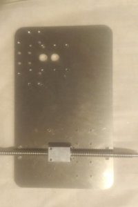
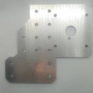
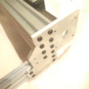
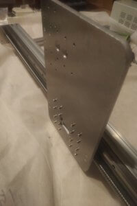
8. Attach the Y axis plates to the linear bearings
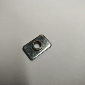
Because we use 12mm ballscrews, that could otherwise touch the Y plates if we would attach them directly to the linear bearings, we need to create some space. This step is a therefore a bit different from the other QueenBee PRO assembly instructions that you will find elsewhere:
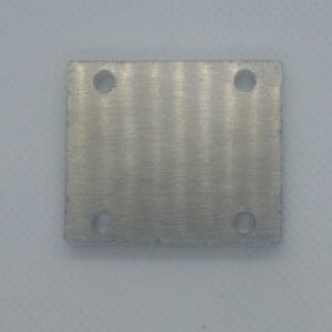
It requires a 1mm spacer plate between each linear bearing and Y plate:
If you have CNC machined black plates, then you also need an extra 6mm spacer plate (on top of the 1mm spacer plate.
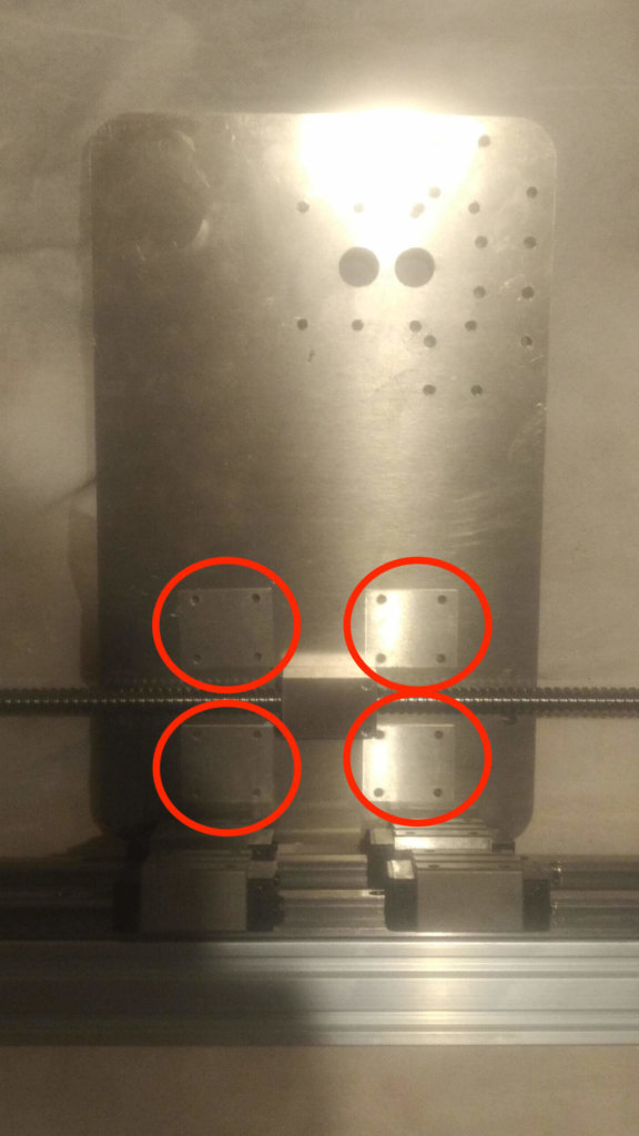
Then use M4 14mm screws to secure the Y plates, and spacers onto the linear bearings:
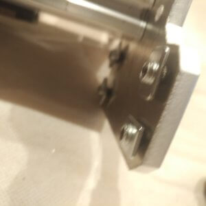
From the other side, see the 1mm spacer between the plate and the linear bearings:
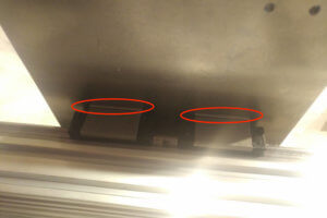
Do this for both Y plates in a way that they are mirrored opposite each-other
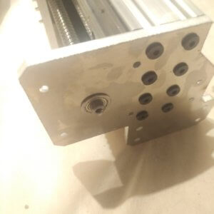
9. Attach the ballscrew floating ends
Put the 8mm end of the ballscrew through the end plate:
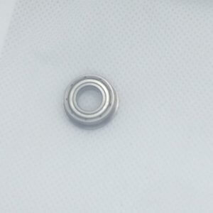
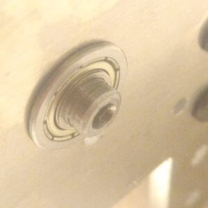
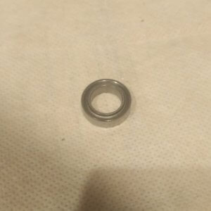
And put a F688ZZ flanged bearing:
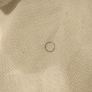
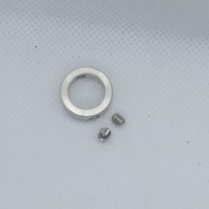
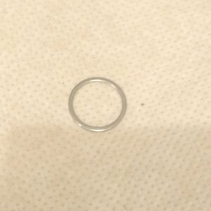
Then put a 8mm precision shim:
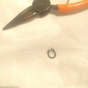
And a circlip – use special tools if needed:
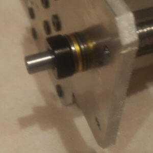
10. Attach the ballscrew fixed (tensioning) ends
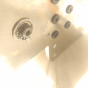
Put the a 10mm lock collar, a 10mm precision shim and a 1016 bearing on the 10mm machined end of the ballscrew:
If you experience some difficulties in putting these on, then it is also sufficient if you just put on the 1016 bearing:
And at the other side, put on a 10mm thrust bearing
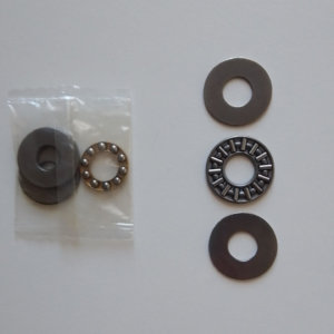
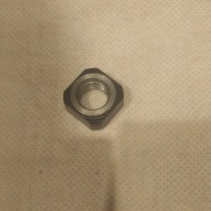
And an M10*1 precision nut to put the ballscrew under some tension – but still to maintain good rotation (must feel smooth rotation):
Done!
And also for the opposite (mirrored) side of course!